Trailer Electrical Plug Wiring Diagram
In the trailer wiring diagram and. Connector wiring diagrams jpg trailer light wiring trailer wiring diagram utility trailer.
Trailer Plug Wiring Diagram 7 Way Flat Trailer Wiring Diagram

Trailer electrical connectors come in a variety of shapes and sizes.

Trailer electrical plug wiring diagram. The wiring diagram is generally made use of in electric engineering to plan the positioning of electric circuits. Trailer wiring diagrams one of the most important parts of fitting a towbar to your vehicle is connecting the electrics from the towing vehicle to the trailer or caravan that you are towing. Besides the three main lighting functions, additional pins for.
Plug size is similar to an australian 10c coin. As a professional rv transporter i have seen to many trucks wired with those 2 wires to small and cause a fire from overheating. Various styles of connectors are available with four to seven pins to allow transfer of power for the lighting as well as auxiliary functions such as electric trailer brake control,.
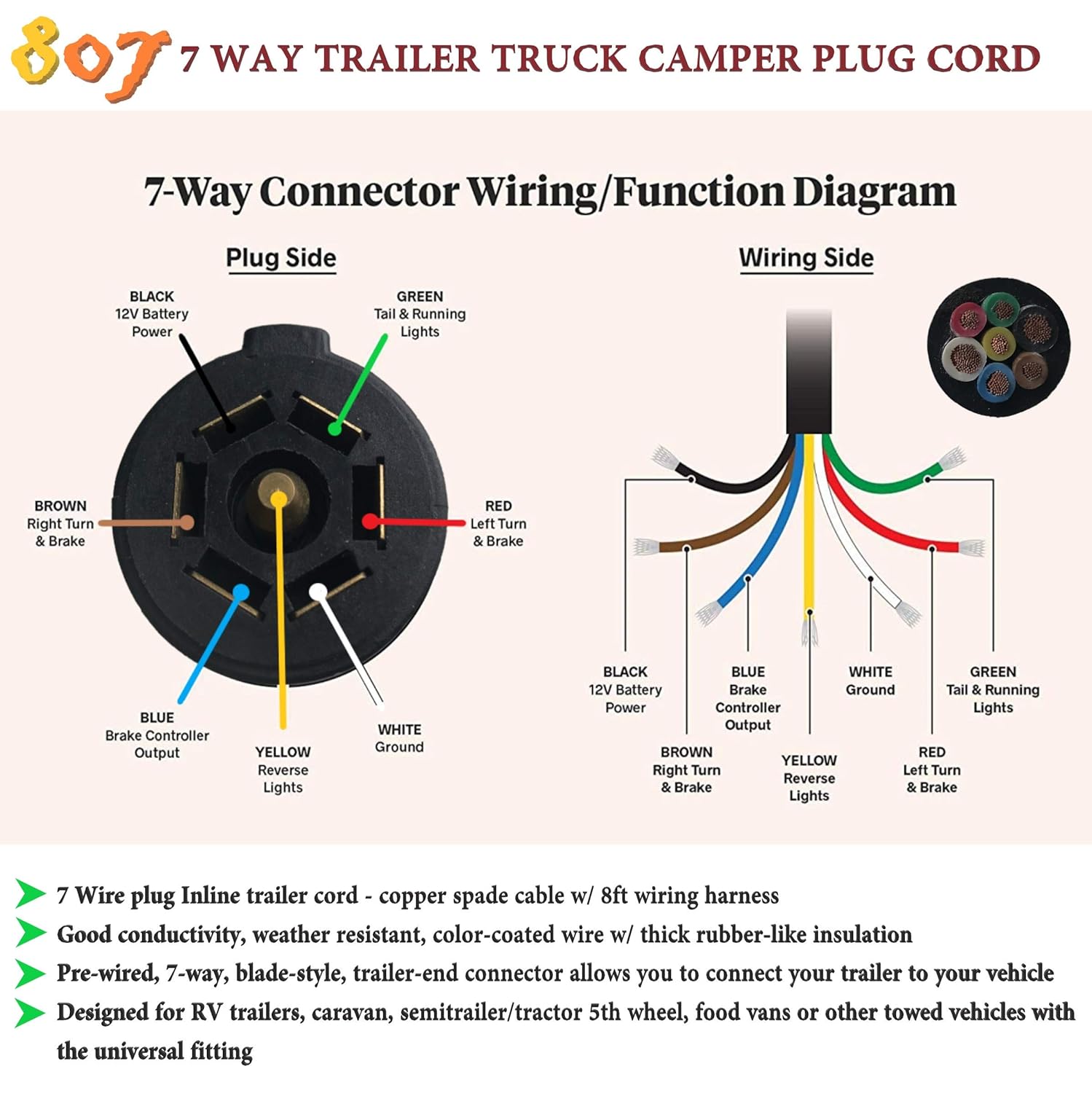
Left brake light left turn signal: Wiring diagram for trailer plug with electric brakes wiring diagram is a simplified usual pictorial representation of an electrical circuitit shows the components of the circuit as simplified shapes and the faculty and signal links along with the devices. The black (12v) and blue (electric brakes) may be reversed to suit trailer.
Power for all normally on lamps. Variety of dodge trailer wiring diagram 7 pin. Which wire is the ground wire on sundowner horse trailer 6 way.
The 7 pin flat plug will fit into a 12 pin flat socket and work perfectly. The first diagram is a simple set up of two brake lights, two indicators and two side lights. Dodge 7 way trailer plug wiring diagram.
*pins 2 and 5 are not used on our standard range of trailers. Verify the harness color codes at each tail light. Connector style pin function color description;
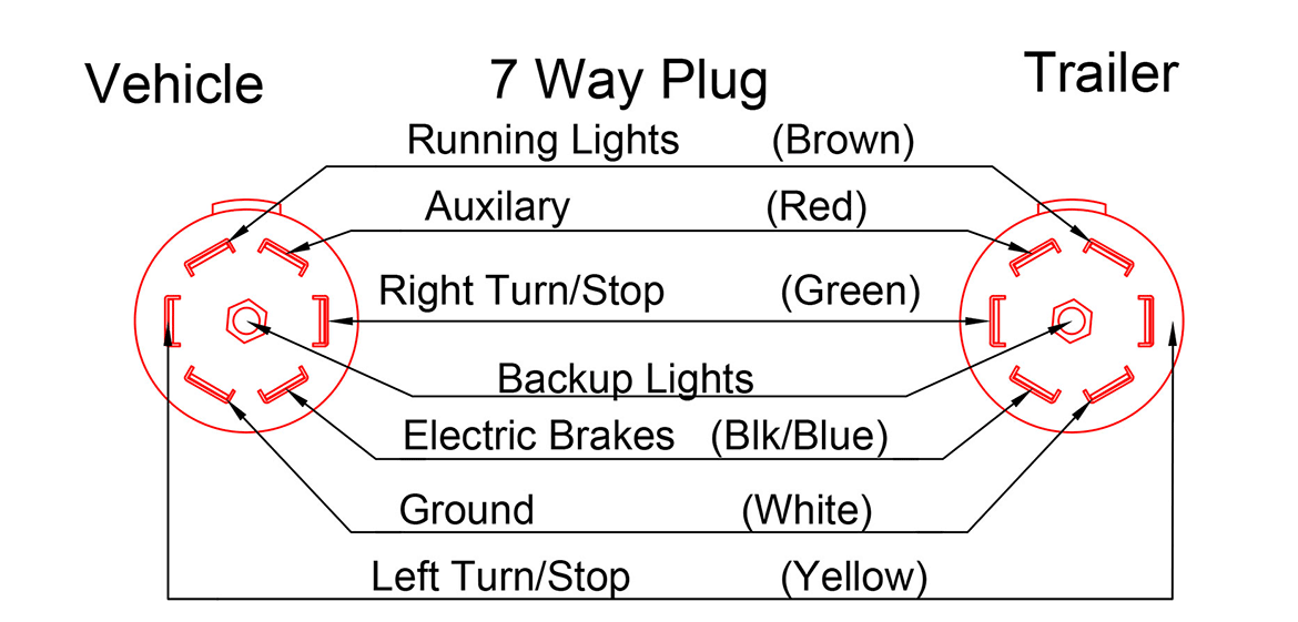
Wiring diagram trailer plugs and sockets. 7 way plug wiring diagram standard wiring post purpose wire color tm park light green battery feed black rt right turnbrake light brown lt left turnbrake light red s trailer electric brakes blue gd ground white a accessory yellow this is the most common standard wiring scheme for rv plugs. 11/10 for 2011 wiring diagrams note:
7 way plug wiring diagram standard wiring* post purpose wire color tm park light green (+) battery feed black rt right turn/brake light brown lt left turn/brake light red s trailer electric brakes blue gd ground white a accessory yellow this is the most common (standard) wiring scheme for rv plugs and the one used by major auto manufacturers today. The second diagram shows two brake lights, two indicators, two side lights and a fog light. This is accomplished by tapping into the tow vehicle's electrical harness to transfer power to the trailer wiring system.
12 pin flat this is an extension of the 7 pin flat. Narva 7 and 12 pin trailer connectors comply with all relevant adrs. Trailer side car side wiring plug diagram.
Collection of ford 7 pin trailer wiring diagram. Small 7 pin round (qld) identifying: It is extremely simple to attract a wiring diagram;
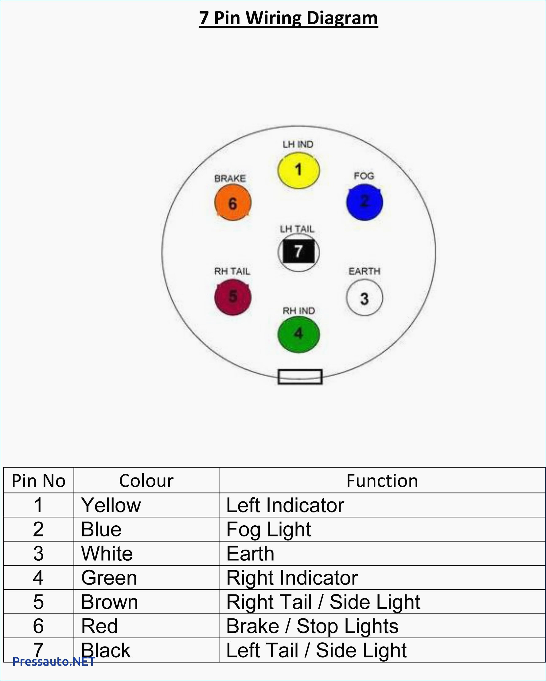
You simply need to have a good comprehension on various types of wiring and their objectives. 7 way trailer wiring diagram is explained in details in the picture and the table below: How to wire up a 7 pin trailer plug or socket trailer wiring diagram trailer light wiring wire.
It is really simple to draw a wiring diagram; Trailer connectors are used between the two to allow disengagement when not towing. All diagrams are as viewed from the cable side.
Click on the image below to enlarge it. 7 way trailer wiring diagram is explained in details in the picture and the table below: Joined may 11, 2014 · 243 posts.
Best of wiring diagram for 7 pin trailer plug uk diagrams digramssample diagramimages wiringdiagramsamp trailer wiring diagram trailer light wiring diagram Wiring diagram ifor williams trailer save wiring diagram horse. Tail lamps running lights side markers:
Australian trailer plug and socket wiring diagrams. A wiring diagram is a simplified standard photographic depiction of an electric circuit. Choose a connector that has the required number of pins for the functions required for your trailer.
Trailer wiring diagrams trailer wiring connectors various connectors are available from four to seven pins that allow for the transfer of power for the lighting as well as auxiliary functions such as an electric trailer brake controller, backup lights, or. 7 pin flat the best! The electrics are required to power the lights on your trailer and, if you own a caravan, the internal electrics inside the caravan, therefore it is important to ensure that it is done correctly.
Horse trailers may use the center pin for 12v hot lead, r.v. The trailer wiring diagram shows this wire going to all the lights and brakes. All diagrams are as viewed from the cable side.
This car is designed not only to travel one location to another but also to take heavy loads. The wiring diagram is generally used in electrical engineering to plan the placement of electrical. You just need to have a great comprehension on various kinds of wiring and their objectives.
To ensure your trailer has safe, visible, and legal lighting, a trailer connector wiring adapter may be a necessary towing accessory. 6 way round trailer plug wiring diagram. Wiring plug diagram created date:
Trailer electrical plug wiring diagram. Trailers use the center pin for electric brakes. In the trailer wiring diagram and connector application chart below, use the first 5 pins, and ignore the rest.
The black (12v) and blue (electric brakes) may be reversed to suit trailer. Never put your trailer on the road with questionable wiring or a lighting system that is already known to be failing. Click on the image below to enlarge it.
Here are two wiring diagrams for the 7 pin ‘n’ type trailer electrical plug. 1110 for 2011 wiring diagrams note. 6 way round trailer side 4 way round trailer side 5 way flat trailer side 7 way pin style car side wire color key 7 way rv blade style car side.
Ground for all trailer electrical functions. The diagram below shows the proper way to wire the connector to your trailer or vehicle. Various connectors are available from four to seven pins that allow for the transfer of power for the lighting as well as auxiliary functions such as an electric trailer brake controller, backup lights, or a 12v power supply for a winch or interior trailer lights.
Tail, running & side marker lights.
5 Pin Trailer Connector Wiring Diagram Trailer Wiring Diagram

Trailer Plug 7 Pin Wiring Diagram Trailer Wiring Diagram

Ford 7 Way Trailer Plug Wiring Diagram Trailer Wiring Diagram

Wiring Diagram For 7 Prong Trailer Plug Trailer Wiring Diagram

Wiring Diagram For 7 Prong Trailer Plug Trailer Wiring Diagram

Trailer Plug Wiring Diagram Australia Trailer Wiring Diagram

wiring diagram for semi plug Google Search Trailer light wiring, Trailer wiring diagram, 5th

7 Pole Trailer Plug Wiring Diagram Collection
7 Way Trailer Plug Wiring Diagram Ford Wiring Diagram
7 Pin Trailer Connector Diagram 6 Prong Trailer Wiring Diagram Wiring Diagram And

7 Way Plug Wiring Diagram Trailer Trailer Wiring Diagram

Wiring Diagram Of A 7 Pin Trailer Plug Trailer Wiring Diagram

Trailer Plug Wiring Diagram 7 Way Chevy Trailer Wiring Diagram

Wiring Diagram For 7 Prong Trailer Plug Trailer Wiring Diagram

Trailer Plug Wiring Diagram 7 Way Collection Wiring Diagram Sample
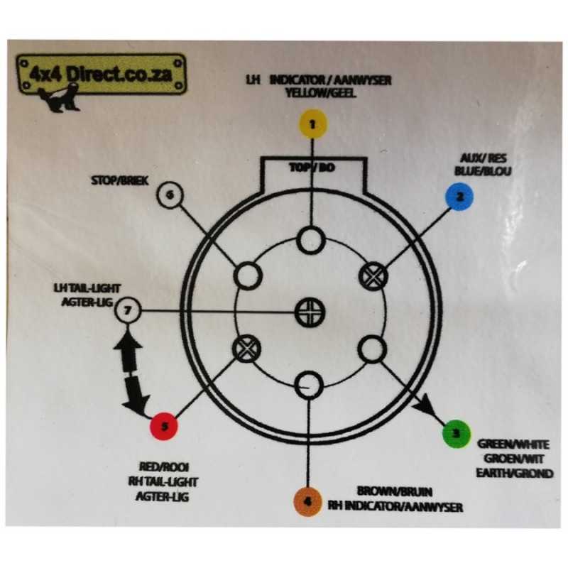
Sticker Trailer Plug wiring diagram
Trailer Plug Wiring Diagram 7 Way Uk Trailer Wiring Diagram

7 Pin Trailer Plug Wiring Diagram Database Wiring Diagram Sample
Heavy Duty 7 Way Trailer Plug Wiring Diagram just wiring
