Float Switch Diagram Wiring
Float switch installation wiring and control diagrams apg septic pump float switch wiring diagram download septic tank float. At times, the cables will cross.
Rule A Matic Float Switch Wiring Diagram

For example look at the chassis battery is stated as 12v 20ah.

Float switch diagram wiring. Float switch controlled water level controller circuit homemade projects. One trick that we 2 to print the same wiring plan off twice. The electrical wire needs to be fixed in a position that isn’t going to change the depth of the float switch, as seen in figure 2.
This is perfectly normal and the correct way to do it.) According to earlier the traces in a septic tank float switch wiring diagram signifies wires. Jul 31, finally, an easy to read diagram.
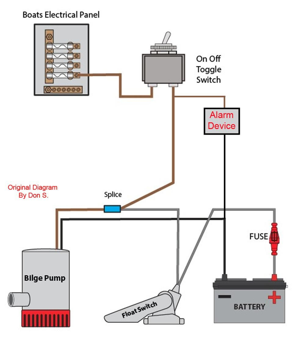
Since jun 28, how to wire a bilge pump with float switch: According to earlier, the traces in a septic tank float switch wiring diagram signifies wires. A float switch consists of the floating switch and the electrical wire.
It can either be fixed to a bracket on top of the water tank, or. The 'float' part of the switch simply goes up and down. When you employ your finger or even the actual circuit along with your eyes, it may be easy to mistrace the circuit.
Jan 24 18 02 09 pm. Connect the a1 terminal of the contactor with terminal '1' of the selective switch. 3 backlit bilge rocker switch wiring diagram of the three bilge pump switches the only one thats not extremely simple is the backlit.
Wiring diagram of 2 float switch for two tanks wiring diagram of 3 motors diagram guitar fender also well and septic systems diagnostics. Float switch connection single phase water pumpwhat is float switch?float switch is a type of level sensor a device used to detect the level of liquid within. In this design the switch sits a top of the mash via an adjustable plastic tube that also protects the wiring.
How single point & multi point switches work. Put a switch according to the diagram how will the pump get power from the float switch is this just. It contains instructions and diagrams for various kinds of wiring techniques as well as other products like lights, windows, etc.
Float switch installation wiring how to wire a tameson com diagram skyhooks and cable with 3 mtrs install an automatic pump controller bilge maretron equipment 9 19 eur 2m 250v 16a continuous level sensor terry love 110 220 fuel tank selector controlled water single phase. Bilge pump wiring diagram with float switch collection the best out of the ordinary is always to use a verified and accurate wiring diagram for float switch on a bilge pump that’s provided from a trusted source. Mar 30, wiring johnson bilge pump the salty dogs.
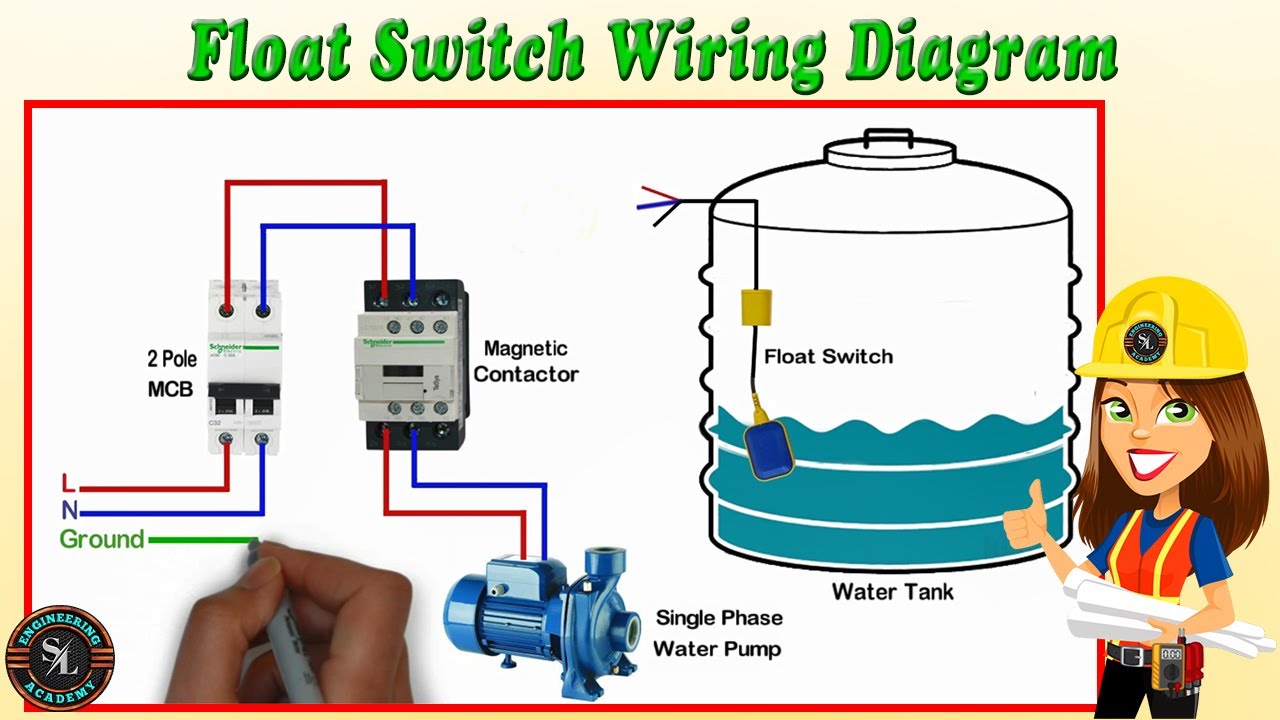
Connect all three phases to the input of the contactor. 3 wire float switch wiring diagram from tonetastic.info. The float switch has two legs.
43 testing and analysis 62. Float switch controlled water level controller circuit homemade projects. For example water level controls is a float switch manufacturer that is revolutionizing the way float switches are used for water level sensing.
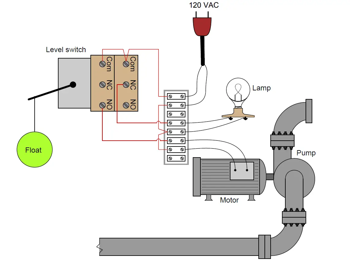
How new float switches work. Typically, they share a common wire to complete the circuit. For wiring instructions, refer to the user manual, or our new float switch wiring guide.
One leg of the float switch will connect to the hot wire from the panel; The other leg will connect to the hot wire from the pump. The wiring or most of the switch for that matter is never in the mash water.
Connect the motor terminals to the output of the thermal overload relay as shown in the above figure. As the liquid level goes up or down, it moves vertically with the liquid level. Let’s start with the most basic float switch:
220v 3 wire well pump wiring diagram. A float switch is a mechanical switch that floats on top of a liquid surface. Let s start with the most basic float switch.
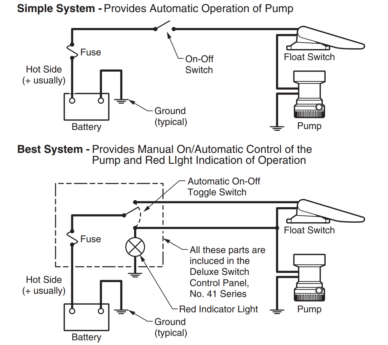
It shows what sort of electrical wires are interconnected and may also show where fixtures and components may be coupled to the system. In a single point float switch, a low alarm sensor will trigger an led light on your control board. In a multi point float switch, a low alarm could trigger the led light to turn on and send a signal to turn on an automatic water pump to refill the water back to the preprogrammed water level.
Each kari float switch model will have a different number of conductors that need to be wired into different places. Print the cabling diagram off in addition to use highlighters in order to trace the routine. But, it doesn’t imply link between the wires.
Injunction of 2 wires is usually indicated by black dot to the junction of two lines. This circuit can be used to fill a water tank automatically. Wiring diagram of 2 float switch for two tanks wiring diagram of 3 motors diagram guitar fender also well and septic systems diagnostics.
However, some of the models have isolated switch points that you can wire to a. 3 wire float switch wiring diagram. Most float switches have a white and black wire, which means you will most likely have a white to black connection.
The meaning is this can power the currents of 20 amps per hour. Rule a matic float switch wiring diagram its new improved blocked wiring for greater durability and water resistance has again raised the standard. There’ll be principal lines that are represented by l1, l2, l3, and so on.
Connect the four pole mcb as input control as shown in the above figure. Float switch wiring ad general installation 𝐅𝐥𝐨𝐚𝐭 𝐒𝐰𝐢𝐭𝐜𝐡 𝐖𝐢𝐫𝐢𝐧𝐠 𝐃𝐢𝐚𝐠𝐫𝐚𝐦 𝐒𝐑𝐊 how to wire a tameson com switches control pilot devices cable with 3 mtrs create pump circuit tank level diagram continuous sensor did i. 2 built in bilge running indicator.
A wiring diagram is a straightforward visual representation with the physical connections and physical layout of an electrical system or circuit. When it goes down all the way it turns on the pump.
float switch wiring diagram for water pump YouTube

18 Awesome Rule Float Switch Wiring
Floattype Level Switch to Control a pump Instrumentation Tools
Tank Float Switch Wiring Diagram Dual Complete Wiring Schemas
Float Switch Installation Wiring & Control Diagrams APG

Dual Float Switch Wiring Diagram For Your Needs

Septic Pump Float Switch Wiring Diagram Free Wiring Diagram

Float Switch Wiring Diagram with Manual On/Off Switch in 2021 Switch, Float, Engineering science

🔥float switch wiring diagram for water pump🔥 YouTube

3 Wire Float Switch Wiring Diagram easywiring

Float Switch Installation Wiring & Control Diagrams APG

Float Switch Installation Wiring & Control Diagrams APG

Bilge Pump Float Switch Wiring Diagram Cadician's Blog
Yacht Devices News Smart Relay our first nonNMEA product
20 New Float Switch Circuit Diagram

Rule A Matic Plus Float Switch Wiring Diagram Wiring Diagram

Needing a wiring diagram for a Johnson 3wire electronic float switch?

Float Switch Wiring Diagram for Water Pump/ How to Make Automatic OnOff Switch for Water Pump
Float Switch Guide and Float Switch Products Madison Company
